
The KCRC TechNet Puzzles For 2019 and 2020
(Click Here For TechNet Puzzles for 2017)
(Click Here For TechNet Puzzles for 2018)
(Click Here For TechNet Puzzles for 2021)
(Click Here For TechNet Puzzles for 2022)
(Click Here For TechNet Puzzles for 2023)
(Click Here For TechNet Puzzles for 2024)
The KCRC TechNet Puzzle for December 23, 2020
In a superhet receiver, which stage provides the bulk of the gain?
A) The detector
B) The mixer
C) The RF stage
D) The IF stage
And now for the answer to our December 23, 2020 TechNet Puzzle
(It is in “Invisotext” and will be visible if you highlight the area below!)
‘A’, the detector demodulates the Intermediate Frequency (IF) signal into something that an audio circuit and your ears can handle and does not that much gain to the signal.
‘B’, the mixer stage just mixes the incoming RF signal with a local oscillator and then filters it to provide an IF signal for later radio stages. It too does not offer much in the way of signal gain.
‘C’, the RF stage does offer some RF filtering to limit desensing from off frequency signals as well as some RF amplification, but not that much.
‘D’, the IF stage is where the ‘magic’ happens. By heterodyning the input RF signal to a single constant frequency, filters and amplifier circuits can be optimized for that single frequency better and more efficiently – it is in this stage that the most of the signal gain is implemented.
And so, the best answer to this question is ‘D’, the IF stage!
.
The KCRC TechNet Puzzle for December 9, 2020
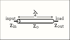
A load with an impedance of 225 ohms is fed via a quarter wavelength section of coax (impedance 75 ohms).
The impedance at the input is:
A) 10 ohms
B) 25 ohms
C) 50 ohms
D) 125 ohms
And now for the answer to our December 9, 2020 TechNet Puzzle
(It is in “Invisotext” and will be visible if you highlight the area below!)
For this question you need to know about ‘Quarter-wave impedance transformers’ (https://en.wikipedia.org/wiki/Quarter-wave_impedance_transformer#:~:text=A%20quarter%2Dwave%20impedance%20transformer,with%20which%20it%20is%20terminated.)
One of the things that you need to remember is the equation:
Zin = ZO2 / Zout
752 / 225 = 25
So, the correct answer for this question is ‘B”, 25 ohms.
The KCRC TechNet Puzzle for November 25, 2020
The ‘mixer’ stage of a superheterodyne receiver is so called because in it:
A) the intermediate frequency mixes with the incoming signal
B) the carrier insertion oscillator mixes with the intermediate frequency
C) the local oscillator mixes with the carrier insertion oscillator
D) the local oscillator mixes with the incoming signal.
And now for the answer to our November 25, 2020 TechNet Puzzle
(It is in “Invisotext” and will be visible if you highlight the area below!)
The history of the Superheterodyne Receiver is a remarkably interesting one. Some credit Walter Hans Schottky of the Schottky Diode, as having the first patent for the technology. Wikipedia gives the honor of the inventor of the technology to a French Engineer Lucien Lévy, but most people still give that honor to the brilliant Electrical Engineer Edwin Armstrong. If you are interested in reading more about the history of this technology, you can find an excellent article at https://www.electronics-notes.com/articles/history/radio-receivers/superheterodyne-radio-receiver.php .
Wikipedia, quite rightly, define a superheterodyne radio as “…a type of radio receiver that uses frequency mixing to convert a received signal to a fixed intermediate frequency (IF) which can be more conveniently processed than the original carrier frequency.”
Answer “A” reverses the whole nature of the IF mixer in a superheterodyne receiver and is wrong. Answer “B” describes how a Single Side Band demodulator operates, not the IF mixer of a superheterodyne receiver. Answer “C” creatively mixes up parts of both the IF mixer AND the SSB demodulator, which are not directly connected in any radio receiver design, so that is certainly wrong.
Which leaves us with answer “D”. A superheterodyne radio has a stage where the incoming RF signal is mixed with the output of a variable local oscillator. The mixer outputs a ‘difference’ signal which is a constant intermediate frequency (IF), for which later circuits can more easily manipulate, rather than when they need to apply the same processes to different frequencies across the receiver’s tunable band.
As is now apparent, answer “D” is the correct answer for this question!
The KCRC TechNet Puzzle for November 11, 2020
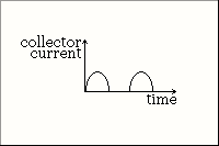 This graph shows the collector current of a transistor amplifier. In what Class is the amplifier biased?
A) Class A
B) Class AB
C) Class B
D) Class C
And now for the answer to our November 11, 2020 TechNet Puzzle
(It is in “Invisotext” and will be visible if you highlight the area below!)
Unfortunately, understanding the different amplifier class designations is necessary to know which answer is correct.
A class A amplifier amplifies an alternate current during the entirety of its signal. Class B amplifiers only amplify its input signal during half of its signal cycle (either the positive or the negative portion of the signal). Class AB is a mix between class A and B amplifying the signal during more than 50% of its signal, but less than 100%, and class C amplifies its signal during less that 50% of its input signal.
The illustration shows the transistor amplifier outputting current during only 50% of a sine wave signal input, so the best answer is “C” Class B amplifier!
.
The KCRC TechNet Puzzle for October 28, 2020
On 80 meters, the DX comes in at night. Why is this?
A) Local interference is at a minimum.
B) Signals are not absorbed by the D layer.
C) Noise level on the band is less.
D) The air temperature is lower.
And now for the answer to our October 28, 2020 TechNet Puzzle
(It is in “Invisotext” and will be visible if you highlight the area below!)
“The ionosphere extends from 37 to 190 miles (60-300 km) above the earth’s surface. It is divided into three regions or layers: The F-Region, E-Layer and D-Layer. During the daytime, the F-Layer splits into two layers then recombines at night.
The E-Layer was discovered first. In 1901, Guglielmo Marconi transmitted a signal between Europe and North America and showed that it had to bounce off an electrically conducting layer about 62 miles (100 km) altitude. In 1927, Sir Edward Appleton named that conducting layer the (E)lectrical-Layer. Additional conducting layers discovered later were simply called the D-Layer and F-Layer.
Since the ionosphere’s existence is due to radiation from the sun striking the atmosphere, it changes in density from daytime to nighttime. All three layers are denser during the daytime. At night, all layers decrease in density with the D-Layer undergoing the greatest change. At night, the D-Layer essentially disappears.”
Most of the time Hams see an energized ionosphere as very helpful to propagate our radio signals to far distances (DX), but this isn’t the case on the lower bands like the 160 meter, or the 80 meter band. An energized D-Layer will absorb and obscure signals on 160 meters and 80 meters. Because of this fact, the correct answer for this question is ‘B’, “Signals are not absorbed by the D Layer”
The KCRC TechNet Puzzle for October 14, 2020
If an AM signal is 100% modulated with a sine wave audio tone, the amplitude of each of the sidebands is:
A) half that of the carrier.
B) equal to that of the carrier
C) twice that of the carrier
D) four times that of the carrier
And now for the answer to our October 14, 2020 TechNet Puzzle
(It is in “Invisotext” and will be visible if you highlight the area below!)
“When the carrier is fully modulated i.e. 100% the amplitude of the modulation is equal to half that of the main carrier, i.e. the sum of the powers of the sidebands is equal to half that of the carrier. This means that each sideband is just a quarter of the total power.”
So, the best answer for this question is ‘A’, “Half that of the carrier”.
The KCRC TechNet Puzzle for September 23, 2020

The time constant of the capacitor / resistor combination shown here is 4 seconds.
How long after the switch is closed will the capacitor be virtually fully charged?
A) 10 seconds
B) 20 seconds.
C) 30 seconds
D) 40 seconds
And now for the answer to our September 23, 2020 TechNet Puzzle
(It is in “Invisotext” and will be visible if you highlight the area below!)
The time constant of a capacitor and resistor in series is called the RC Time Constant, τ (Tau). It is equal to the product of a circuit’s resistance, in ohms, times a circuit’s capacitance in Farads. It is the time required to charge a capacitor through a resistor form an initial charge of 0 volts up to, approximately 63.2% of the voltage applied to the circuit.
Below you can see a graph of the voltage rise in a capacitor over time of an RC Circuit with 10 Volts applied:

(this is based upon the equation: V(t) = V0(1-e-T/ RC)
As you may notice the charge never comes to 100% of the applied voltage, it keeps getting closer and closer but only reaches it at infinity. There is no computer monitor wide enough to show the end of a graph that goes on until infinity.
If we write any given RC circuit’s Time Constant as RC, then as the charge time continues the capacitor will reach a higher voltage potential charge:
T = 1RC 63.2% Voltage Percentage of source
T = 2RC 86.5% Voltage Percentage of source
T = 3RC 95.0% Voltage Percentage of source
T = 4RC 98.2% Voltage Percentage of source
T = 5RC 99.3% Voltage Percentage of source
From there the Voltage Percentage of source sneaks more and more slowly to 99.9999999999999999999999999999999999999999999999999999999999999999…%
You get the idea.
But Electrical Engineers do not have time for infinities, so for the sake of brevity they have all agreed that any given RC circuit can be considered to be virtually fully charged at a time of 5 times its time constant.
In the above case, five times its time constant, 4 seconds, comes to 20 seconds – that is answer “B”
And so, answer “B” 20 seconds is the best answer for this question!
The KCRC TechNet Puzzle for September 9, 2020

In this block diagram of a crystal-controlled CW transmitter, what does box T represent?
A) x2 multiplier stage.
B) modulator
C) SWR meter
D) x3 multiplier stage
And now for the answer to our September 9, 2020 TechNet Puzzle
(It is in “Invisotext” and will be visible if you highlight the area below!)
This puzzle may seem ‘deceptively’ easy, but it really is!
The crystal oscillator is indicated to oscillate at 3.5 MHz, there is a ‘X2 Multiplier Stage’ indicated in the block diagram later in the chain, but that only brings the frequency up to 7 MHz, rather than the 14 MHz indicated at the final power amplification stage.
There are only two choices that are ‘multiplier’ stages – “A”, which is a 2X multiplier stage and “D” that is a 3X multiplier stage.
If you chose “D” the frequency would be multiplied in the following way:
3.5 MHz x 3 x 2 = 21 MHz.
But that’s the wrong transmitter frequency!?
If you chose “A” the frequency would be multiplied in the following way:
3.5 MHz x 2 x 2 = 14 MHz.
So, obviously “A”, x2 multiplier stage, is the correct answer!
.
The KCRC TechNet Puzzle for August 26, 2020
Refraction in the troposphere often results in:
A) increased ionization of the D region
B) an increase in the number of sunspots
C) VHF. signals being received at great distances.
D) auroral displays
And now for the answer to our August 26, 2020 TechNet Puzzle
(It is in “Invisotext” and will be visible if you highlight the area below!)
For this puzzle, you must keep in mind the atmospheric layers of our Earth:
The Troposphere is the lowest layer of our atmosphere, and the part we breathe, as well as the part where most of the weather happens. It extends from the surface of the Earth up to about 5 to 9 miles high!
Above that is the Stratosphere, that extends up to 31 miles above the surface of our Earth – This contains the famous Ozone Layer , where most of the Sun’s dangerous UV rays are safely blocked from ionizing all our DNA and giving us sundry forms of cancers.
Above that is the Mesosphere, that extends up to 53 miles high – this is where most meteors burn up before they can crash down upon us!
Above that is the Thermosphere, that extends up 372 miles high – this is were the Aurora Borealis and the Aurora Australis hang out, as well as the ISS and most Low Earth Orbit (LEO) satellites.
Superimposed upon other layers, like the Mesosphere , the Thermosphere, there’s the Ionosphere, which is very important to Hams concerned about propagation conditions, it extends about 30 miles above the surface of the Earth as far up as 600 miles high!
Then, there is the Exosphere, the very upper limit of our atmosphere, extending from the edge of the Thermosphere, up to 6,200 miles!
With those facts in mind, you can see that things going on in our Troposphere have little to no effect upon the D layer of our Ionosphere (answer “A”), nor the Auroras in the Thermosphere (answer “D”).
Sunspot activity on the Sun may affect the weather in our Troposphere, but it doesn’t work the other way around – the Sun is indifferent to our Earthly weather patterns, so answer “B” is definitely wrong.
That leaves us only with answer “C”.
During some weather patterns with high pressure zones, and nearby large bodies of water, there is a thermal inversion in the Troposphere, which causes a phenomenon called Tropospheric Ducting. When this happens VHF signals, rather than flying into outer space are refracted within the Troposphere, bending back to Earth and propagate much farther than usually seen. This is how Hams on the West Coast can communicate with Hawaiian stations using VHF, and why repeaters from Massachusetts and Pennsylvania can sometimes clearly be heard locally, instead of our local repeaters!
So, the correct answer to today’s puzzle is: C) VHF signals being received at great distances (tropospheric ducting).
The KCRC TechNet Puzzle for August 12, 2020

This figure shows the characteristics of a Zener diode. Which section of the graph is used for voltage stabilization?
A) Section A
B) Section B
C) Section C
D) Section D
And now for the answer to our August 12, 2020 TechNet Puzzle
(It is in “Invisotext” and will be visible if you highlight the area below!)
This one is relatively easy if you remember how Zener diodes work.
A perfect diode does not exist. That is why, when you look up the specifications for any diode, you will find the following characteristics specified: Forward Voltage Drop, Peak Inverse Voltage, Reverse Breakdown Voltage, Maximum forward current, Junction operating temperature, and Junction to ambient thermal resistance.
Depending on how a given diode is designed, these factors can be modified to suit the circuit designer.
The ‘magic’ of a Zener diode is in the design for its Reverse Breakdown Voltage, specifically its ability to tolerate a large reverse current flow without complete diode failure!
By reverse biasing a Zener diode you can obtain a reference voltage that is its Reverse Breakdown Voltage, that can act as a quick and dirty voltage regulator
This aspect of the Zener Diode is shown in Section ‘D’ of the curve illustrated above.
So, the correct answer is ‘D’ – Section D.
The KCRC TechNet Puzzle for July 22, 2020

The figure above shows a low voltage power supply, using a full wave bridge rectifier. The transformer has a 12 V secondary winding.
To which range should the meter be switched?
A) 12 V A.C.
B) 12 V D.C.
C) 20 V A.C.
D) 20 V D.C.
And now for the answer to our July 22, 2020 TechNet Puzzle
(It is in “Invisotext” and will be visible if you highlight the area below!)
You can use simple logic to help you with this question – the point of a full-wave bridge rectifier is to turn alternating current (AC) into direct current (DC), so answers “A” and “C” are wrong to begin with.
Now we are left with either 12 volts DC or 20 volts DC as the possible answer…
You would think that the schematic itself indicates that the transformer is designed to step down a 240 volt power source down to 12 volts, so 12 volts should be the answer, right?
Well, that’s where the tricky part comes in. You see, those voltages, 240 and 12, are Root Mean Square (RMS) averages of the voltage supplied. What you are really interested in is finding out the Peak To Peak voltage.
I’ll spare you the math. It comes to:
VRMS = VPeak/sqrt(2)
So, the peak voltage for an RMS of 12 is 12 x 1.414 = about 16.8 volts!
If your smoothing capacitors were perfect, you might get away with a 12 volt setting, but just to be on the safe side, setting your meter to full deflection at 20 volts is the preferable setting.
So, answer “D” 20 volts DC is the best answer.
The KCRC TechNet Puzzle for July 8, 2020
To decrease the sensitivity of a receiver, which of its controls should be switched in?
A) Notch filter.
B) AGC
C) Attenuator.
D) Clarifier.
And now for the answer to our July 8, 2020 TechNet Puzzle
(It is in “Invisotext” and will be visible if you highlight the area below!)
A Notch Filter attenuates signals in a specific frequency range, but they do not affect the sensitivity of a receiver, so answer “A” is wrong.
An AGC is an Automatic Gain Control is a closed feedback loop that regulates the gain of an amplifier to maintain an appropriate signal amplitude – it can increase or decrease your receiver’s effective sensitivity, so answer “B” is wrong.
A Clarifier may be better known as a Receiver Incremental Tuning, or RIT shifts the receiver’s receiving frequency higher or lower, when you speak to someone, not transmitting exactly on your frequency in Single Side Band – it has no effect of the radio’s gain, so “D” is wrong.
The correct answer is “C” Attenuator – an Attenuator decreases the signal’s amplitude without distorting its waveform – effectively lowering its sensitivity when switched into the radio circuit.
The KCRC TechNet Puzzle for June 24, 2020

This figure shows a radio wave sent horizontally from a transmitter. In what part of the radio spectrum is the frequency of this wave?
A) Below the critical frequency.
B) Between the critical frequency and the maximum usable frequency.
C) Above the maximum usable frequency.
And now for the answer to our June 24, 2020 TechNet Puzzle
(It is in “Invisotext” and will be visible if you highlight the area below!)
First, let us look at the illustrations. It appears to show a radio wave transmitted on the surface of the Earth. After entering the ionosphere, the radio wave is refracted, BUT not enough to attain a ‘critical angle’ when refraction causes internal reflection of the radio wave back to the Earth. Instead this radio wave still passes completely through the ionosphere and into outer space, never to be heard again.
The Critical Frequency is defined as: “the highest magnitude of frequency above which the waves penetrate the ionosphere and below which the waves are reflected back from the ionosphere at vertical incidence.” It is NOT the highest frequency which is reflected from the layer – the Maximum Usable Frequency is the maximum frequency which can be reflected for a given distance of transmission
This is not happening in the illustration, so it is above its critical frequency and answer “A” is wrong.
The illustration shows the radio waves NOT being reflected back to the Earth, so its frequency MUST be above the Maximum Usable Frequency…
So, “B” is wrong.
And “C” is right! The transmission must be above the Maximum Usable Frequency!
The KCRC TechNet Puzzle for June 10, 2020
A transmission line terminated by its characteristic impedance:
A) needs no balun
B) appears to be infinitely long.
C) radiates evenly along its entire length
D) has a high SWR
And now for the answer to our June 10, 2020 TechNet Puzzle
(It is in “Invisotext” and will be visible if you highlight the area below!)
So, let’s take a look at answer “A”: When a transmission line is terminated by a load of the same, exact impedance value, the transmission line is able to transfer all of its power into the load. Only an impedance mismatch causes energy to be reflected in the opposite direction, where a balun might come in useful. Baluns are also useful for impedance mismatches, which is clearly not the case in this puzzle.BUT they might still be useful in handling a balanced transmission line, feeding a unbalanced load, or vice versa. This answer is close to right, but not completely right!
So, the answer isn’t “A”.
As far as answer “C”, a transmission line with an identical impedance load at its end does not reflect back anything in common mode. The only mode that is operation is differential mode. The great thing about differential mode, is that it does not radiate RF in the transmission line.
So, “C” isn’t right, either.
On to answer “D”: When you terminate a transmission line with the same impedance as the transmission line, but definition, your resultant VSWR is 1:1, which ain’t ‘high’.
So, answer “D” is wrong.
If you have one of those new fangled Vector Network Analyzers that also are called antenna analyzers, thy often feature something called a Time Delay Reflectometer – these devices ‘ping’ a transmission line and then listen the time delay and amplitude of any signal that is reflected back. Using this you can figure out if the coax is faulty, or id connectors spliced into your transmission line are reflecting too much power back at you. If you know the speed of the RF in that cable you can even measure its total length with such a device.
If you try to use that TDR on a transmission line with an identical load impedance, you will see nothing every return back – it all goes into that load and is either radiated as RF or waste heat.
It “appears to be infinitely long”…
So, that’s the right answer for this time’s puzzle: “B) Appears to be infinitely long.”
.
The KCRC TechNet Puzzle for May 27, 2020

The voltage / time graph above gives the voltage across the smoothing capacitor in a half-wave rectifier circuit.
The current through the diode rectifier is depicted in graph:
A ?
B ?
C ?
Or D ?
And now for the answer to our May 27, 2020 TechNet Puzzle
(It is in “Invisotext” and will be visible if you highlight the area below!)
First let’s consider what the curve would look like if it were simpler. If instead of a smoothing capacitor the rectifier bridge were just connected to a simple resistor.
In that case the curve for a full bridge rectifier, it would look like graph ‘A’, but this isn’t a full wave bridge rectifier, it is a half-wave bridge rectifier, so the graph would look like ‘C’.
Now, we need to imagine what the addition of a smoothing capacitor.
During each half-wave that the rectifier conducted, the smoothing capacitor would draw a current from the conducting diodes until it was fully charged. When the capacitor approached its full charge, it would no longer draw any current from the diodes. As the voltage potential from the diode drops due to the alternating current power supply, the capacitor discharges and supplies current to its external load. The only current from the diode during the next ‘cycle’ is to replace the charge drawn off from the external power load.
So, although the final current coming from the smoothing capacitor is close to a horizontal straight line, like the very first graph, the actual current drawn from the half wave rectifiers are even choppier than the simpler half rectified current going directly into a pure resistive load.
The choppiest graph is ‘D’ and that is the graph that shows the current being drawn from the half wave rectifier into a smoothing capacitor.
The KCRC TechNet Puzzle for May 13, 2020

Which of the following can be measured by the moving coil meter in this diagram?
1. DC voltages
2. AC voltages
A) Neither of them.
B) (l) only.
C) (2) only.
D) Both (1) and (2).
And now for the answer to our May 13, 2020 TechNet Puzzle
(It is in “Invisotext” and will be visible if you highlight the area below!)
If you take a look at the schematic, you will see a current detecting galvanometer with a number of different resistors that can be switched into series with the galvanometer. They are termed multiplier resistors, and this is another example of a voltmeter that we have been discussing in earlier puzzles.
There is ONE additional feature to this voltmeter, and that is the four diodes being included. If you have seen schematics of power supplies, you might recognize these diodes arranged to be a full wave bridge rectifier.
A full wave bridge rectifier uses four individual rectifying diodes, connected in a closed loop, or a “bridge” configuration, to produce current always going in the same direction, even though the original current’s direction is alternating back and forth with each cycle.

Without the full rectifier bridge your voltmeter would be useful to measure a DC, direct current voltage potential, but an alternating voltage potential, faster than the galvanometer’s meter inertia would cause the meter to read ZERO volts, even as the galvanometer overheated, by allowing too much alternating current to melt its coiled wire!
By adding the full bridge rectifier, your voltmeter supplies AC voltage in only one direction and you can measure your AC voltage.
Since the full wave bridge rectifier also passes the DC voltage to the same points in the galvanometer, you can still use it to measure your DC voltages.
So, the correct answer is ‘D’ – Both (1) and (2).
The KCRC TechNet Puzzle for April 22, 2020
Elmer wants to measure a high voltage with a sensitive moving coil meter. In calculating the value of the series resistor to use, he disregards the resistance of the meter itself.
Why?
A) Elmer is lazy.
B) The error this causes is less than the accuracy of the meter.
C) There is no voltage drop across the meter.
D) The resistance of the meter itself is irrelevant.
And now for the answer to our April 22, 2020 TechNet Puzzle
(It is in “Invisotext” and will be visible if you highlight the area below!)
Let me offer you an arbitrary example of a galvanometer that can be used as part of a voltmeter. The specific values of the components will change for other specific galvanometers, but this example will show the orders of magnitude that are involved.
We will choose a sensitive galvanometer with a 100-ohm coil resistance, then a 100-microampere current for its full deflection point. Using Ohm’s law, that would mean that full meter deflection would require a voltage of 10mV across the meter’s terminals.
To design a voltmeter, that required a full-scale reading of 20 Volts, we would need to make sure that 20 Volts would cause 100 microamperes to flow through the chosen galvanometer.
Ohms Law tells us that a resistor of 200K Ohms would pass 100 microAmperes through it, if exposed to 20 Volts. If we were to put our galvanometer in series with this current path, we would have a functioning 20-Volt Voltmeter. But what about the coils own 100 Ohm resistance? Well, the 100 Ohm coil resistance is negligible in comparison to the 200K Ohm resistor, so we can ignore it.
Hey! That is what answer ‘B’ — “The error this causes is less than the accuracy of the meter” says!
So, B is the best answer for this question!
BUT what about choosing the proper shunt resistor to use that galvanometer into a useful ammeter?
Well, to create an ammeter with a maximum current rating of 1 Ampere, the current must generate 10 mV across a “load resistor” or “shunt resistor”. By permitting 1 Ampere to flow through a 10-milliOhm resistor, 10 mV is generated across this resistor. So, we connect the galvanometer across (in parallel with) this 10-milliOhm resistor:
As the galvanometer’s resistance (100 Ohms) is much much greater than the shunt resistance (10-mOhm), we can pretty much disregard the effect of paralleling the galvanometer’s coil to our shunt. The Ammeter created, effectively has 10-milliOhms of resistance, which is pretty much negligible, and reads up to 1 Ampere current.
So, the answer would be similar in the case of a galvanometer and choosing a parallel shunt resistance. The galvanometer’s own internal resistance is insignificant to the high series resistance of a voltmeter’s multiplier resistor, AND the much lower parallel resistance of an ammeter’s shunt resistor!
The KCRC TechNet Puzzle for April 8, 2020
How can a sensitive moving coil meter be used to measure a high d.c. voltage?
A) By fixing a resistor in series with it.
B) By fixing a shunt resistor across its terminals
C) By fixing a large capacitor across its terminals
D) By fixing a rectifier in series with it
And now for the answer to our April 8, 2020 TechNet Puzzle
(It is in “Invisotext” and will be visible if you highlight the area below!)
The ‘sensitive moving coil meter’ mentioned is just an old fashion ‘Galvanometer’ – it can measure very low electrical currents running through its coil, creating a magnetic field, which produces a force to deflect the visible needle, proportional to the current.
That’s great for the microamperes that most galvanometers can work with, but it will fry its coil for most circuit’s currents.
That is why it is very common to see galvanometers that use either parallel ‘shunt resistors’ or serial current limiting resistors.
Ammeters use the galvanometer in series with the circuit under test and use a parallel ‘shunt resistor’ to harmlessly bypass the galvanometer from most of the current going through the test current.
Early Voltmeter designs work differently – it is connected to the test circuit in a parallel configuration, and an accurate known resistance, current limiting resistor, often known as a Voltmeter Multiplier, is placed in series with the galvanometer. Using Ohms’ Law, V = I R, the value of the series resistor and the detected current going through the galvanometer will provide enough information to calculate what the voltage difference between your test probes would need to be for all this to work out correctly.
Choice ‘B’ describe an ammeter, not a voltmeter, choice ‘C’ would cause the galvanometer to burn out, almost immediately, and choice ‘D’ would burn out the galvanometer testing one direction of voltage difference (forward bias) and cause no meter deflection when reverse biased.
So, the correct answer for this question is:
A) By fixing a resistor in series with it.
The KCRC TechNet Puzzle for March 25, 2020
Jackie suspects that the poor signal reports she is getting are due to dampness in the coaxial cable feeding her antenna.
She feeds 20 watts into the cable and gets 10 watts into a dummy load at the other end.
So, the loss in her coax is
A) 2 dB
B) 3 dB
C) 4 dB
D) 6 dB
And now for the answer to our March 25, 2020 TechNet Puzzle
(It is in “Invisotext” and will be visible if you highlight the area below!)
A decibel is a ratio – In the above example the ratio is 10 watts:20 watts, or ½
dB = 10log ½
or
ratio = 1/2 = 10 ^ dB/10
Most people don’t memorize logarithmic tables, and slide rules are pretty much a thing of the past, but there are simple numbers to remember:
Doubling or halving is +/- 3dB
A tenfold increase/decrease is +/-10dB
When you multiply the ratios, you add its decibels
When you divide the ratios, you subtract its decibels
In other words, you can look at an increase by a thousand as:
10 x 10 x 10 = 1,000
In decibels that would be
10dB + 10dB +10dB = 30dB
Just by memorizing 3dB = 2x, and 10dB = 10x you can quickly figure in your head that:
3dB + 3dB = 6dB = 2 x 2 = 4x ratio
And
10 dB – 3dB = 7dB = 10 /2 = 5x ratio
Getting back to the question at hand, when you halve the original signal, you are experiencing 3dB of loss (you can consider it also at -3dB of gain, which would be like a double negative in English).
The correct answer to this question, is: B) 3 dB
The KCRC TechNet Puzzle for March 11, 2020
The value on a dBW scale is given in relation to:
A) 1 mW
B) 1 W
C) 10 W
D) 100 W
And now for the answer to our March 11, 2020 TechNet Puzzle
(It is in “Invisotext” and will be visible if you highlight the area below!)
Decibels are tenth of a ‘Bel’. Bels, named after Alexander Graham Bel, are in themselves unitless ratios – +1 Bel is an increase by 10 times, while -1 Bel is a decrease to 1/10th times. Bels were deemed too large to be useful, so a tenth of a Bel is generally used – the decibel, it just means that 10 decibels = 1 Bel = an increase by 10 times.
Common practice is to add a unit designation after the ‘dB’ term to define what the scale is in relation to – such as dBx, where the unit would be whatever ‘x’ stood for. As an example, the increase or decrease in voltage is designated dBV – a value of 0 dBV is equal to 1 volt, 10 dbV is equal to 10 volts, 20 dBV is equal to 100 volts.
In the case of the unit of power, Watts, a value of 0 dBW is one Watt…
So, the answer to the question above is ‘B’ 1 W.
.
The KCRC TechNet Puzzle for February 26, 2020
The modulation envelope of an AM signal carrying a sine wave is displayed on an oscilloscope. Three complete cycles of the sine wave are shown across the screen. The frequency of the time-base is:
A) One third that of the carrier frequency
B) Three times that of the carrier frequency
C) One third that of the modulating sine wave.
D) Three times that of the modulating sine wave
And now for the answer to our February 26, 2020 TechNet Puzzle
(It is in “Invisotext” and will be visible if you highlight the area below!)
Well, since the oscilloscope is described as taking up three full cycles of the audio modulating waveform, the time base can only be compared to the modulating wave.
An oscilloscope plots voltage against increasing time. The voltage amplitude is displayed in the Y axis and the time is displayed in the X axis – a wave that completes an entire cycle on the oscilloscope’s display is said to have the same cycle period as the oscilloscope’s time base. If the time base is adjusted to half the time period two complete waves will be displayed on the screen…
So, the correct answer to the above question is: ‘C’, one third that of the modulating sine wave.
The KCRC TechNet Puzzle for February 12, 2020
A two-tone oscillator is used in:
A) Measuring the SWR on a transmission line
B) The calibration of an oscilloscope time-base
C) Morse practice transmissions on FM
D) The measurement of the output of an SSB transmitter.
And now for the answer to our February 12, 2020 TechNet Puzzle
(It is in “Invisotext” and will be visible if you highlight the area below!)
A single frequency oscillator will let you test the accuracy of your oscillator’s time base, without a second frequency needed.
Morse code keys your transmitter’s RF oscillator, you select the audio frequency you hear by adjusting the frequency offset of your receiver – no two-tone signals required.
Two tone testing consists of applying two clean non-harmonically related sine waves of approximately equal amplitude to the audio input of an SSB transmitter. The sine waves are typically around 600 – 700Hz and 1800 – 2000Hz i.e. about 300Hz from either end of the audio pass band. The result, in a properly adjusted transmitter, is an RF output that varies from zero to maximum at a rate determined by the difference in frequency between the two audio inputs. Consequently, overdrive (which causes splatter), non-linearity, instability and a host of other problems are easily visible on an oscilloscope. This thorough testing of the transmitting system becomes even more important when the transmitter is followed by a linear amplifier, so as not to compound the problem with more errant RF energy.
So, the correct answer is ‘D’ the measurement of the output of an SSB transmitter.
The KCRC TechNet Puzzle for December 11, 2019
An alternating voltage can be measured with a bridge rectifier and a moving coil meter.
The limit to the sensitivity of such an arrangement is determined by the:
A) voltage drop across the rectifier.
B) momentum of the meter
C) capacitance of the range switch on the meter
D) resistance of the probes
And now for the answer to our December 11, 2019 TechNet Puzzle
(It is in “Invisotext” and will be visible if you highlight the area below!)
Sensitivity is the minimum input magnitude that can be detected and measured. The momentum of the meter might introduce some initial error in the meter reading but is self-corrected in a small interval of time. Capacitance of the range setting rotary switches should not affect the meter’s sensitivity. The resistance of the voltage probes would introduce errors in accuracy of the measured values but would not only limit the device’s sensitivity.
All solid-state rectifiers possess a characteristic forward voltage drop, when forward biased into conducting electricity. Diodes made of different substrates possess different voltage drops – silicon-based diodes have a 0.7V forward voltage drop, while Germanium-based diodes have a 0.3 V forward voltage drop. These voltage drops are independent of the current flowing through the diode.
If the voltage to be measured by the bridge rectifier is below its threshold forward voltage drop it will not rectify ANY current and the meter will be useless. It is this factor in this question, that limits the sensitivity of this measuring device.
The correct answer to this problem is ‘A’ – voltage drop across the rectifier
.
The KCRC TechNet Puzzle for November 27, 2019
Bob is testing a home-brew transmitter. He notices that the voltage from his power supply drops when he keys the transmitter. Bob should test especially for:
A. Key clicks
B. Chirp.
C. Over- modulation
D. Parasitic oscillations
And now for the answer to our November 27, 2019 TechNet Puzzle
(It is in “Invisotext” and will be visible if you highlight the area below!)
For this question you would need to have an understanding about CW transmissions and what leads to degradation of a readable signal
You would think that the best CW transmission would be pure “square waves”:

But when you try this you actually end up with:

Those are heard as ‘key clicks’!
What you REALLY want to transmit are sweeping gradually increasing and decreasing waves:

Over-modulating a CW signal is not easy to do, since it alternates between 0% power and 100%. In theory you can overmodulate it by transmitting ‘sorta CW’ by transmitting AM bursts at the CW tone frequency. So called Modulated CW (MCW) isn’t legal as far as the FCC is concerned, but if you did use it and over-modulated it you would generate harmonics outside of your signal’s normal bandwidth.
Parasitic Oscillations are unwanted oscillations on frequencies other than the one that you are trying to communicate on. They are usually caused by stray resonant circuits in the amplifier chain of your transmitter, not related to your voltage supply’s voltage regulation.
A ‘Chirp’ is a signal whose frequency increases or decreases with time. There are three common causes for this problem:
1) Voltage supply instability due to poor voltage regulation
2) ‘Pulling’ – where the frequency of your transmitter’s other stages change when you key your transmitter.
3) RF Feedback in your transmitter.
To sum it all up, the correct answer is (B) Chirp should be considered if your power supply’s voltage regulation is less than optimum!
The KCRC TechNet Puzzle for November 13, 2019
Which one of these circuits is a T-network?

- Circuit A.
- Circuit B.
- Circuit C.
- Circuit D.
And now for the answer to our November 13, 2019 TechNet Puzzle
(It is in “Invisotext” and will be visible if you highlight the area below!)
This is a relatively easy question IF you know the naming convention. If you draw horizontal lines for series reactance components, and vertical lines for parallel reactance components you can make stick figure similar to a ‘T’ or a ‘L’ or a Pi (π). Here are some illustrations to demonstrate this:

Circuit ‘D’ is an L network, ‘C’ is a Pi network, and ‘B’ is a balanced L network.
Circuit ‘A’ is a T type network.
So, the correct answer is ‘A’!
The KCRC TechNet Puzzle for September 25, 2019
In which category of transmission is the carrier suppressed?
A. FM
B. SSB
C. AM
D. CW
And now for the answer to our September 25, 2019 TechNet Puzzle
(It is in “Invisotext” and will be visible if you highlight the area below!)
I guess that you just have to know how Frequency Modulation, Single Side Band, Amplitude Modulation, and Continuous Wave transmission works.
Suffice it to say, Single Side Band works by suppressing the carrier and either the upper or lower sideband…
So, the answer is “C” SSB!
.
The KCRC TechNet Puzzle for September 11, 2019
The accuracy of a frequency counter is specified as 0.5 parts per million.
If the display reads 2.000000 kHz, the true frequency could be anywhere between:
A. 1.999981 and 2.000019 kHz
B. 1.999987 and 2.000013 kHz
C. 1.999993 and 2.000007 kHz
D. 1.999999 and 2.000001 kHz.
And now for the answer to our September 11, 2019 TechNet Puzzle
(It is in “Invisotext” and will be visible if you highlight the area below!)
First, let’s discuss ‘Percent error”, how many percents ‘off’ an observed value can be from the true value, due to the measurings device’s accuracy in measuring this value.
It is usually expressed as:
Percent Error = [{(Observed Value) – (True Value)} / True Value] x 100 (percent)
It is simple to see that if we want an error rate expressed as Parts Per Million, rather than Parts Per Hundred (percent), we substitute the 100 in the equation with 1,000,000:
Parts Per Million Error = [{(Observed Value) – (True Value)} / True Value] x 1,000,000 (percent)
For the above question, for the highest observed value, with a 0.5 ppm error, the equation can be substituted as:
0.5 = (X-2)/2 * 1,000,000
0.5 * 2/1,000,000 = X-2
0.000 001 = X -2
2.000 001 = X
That would be answer “D” 1.999 999 and 2.000 001 kHz.
The KCRC TechNet Puzzle for August 28, 2019
For a circuit to resonate, an inductor and a capacitor are needed. If the capacitor is replaced by one with four times the value, the frequency of resonance will:
A. Decrease to one quarter of its previous value
B. Be halved.
C. Double
D. Increase by 4 times
And now for the answer to our August 28, 2019 TechNet Puzzle
(It is in “Invisotext” and will be visible if you highlight the area below!)
Remember the puzzle from June 12, 2019????????

Well, if “C” were replaced with “4C” (four times its original value, then its resonant frequency would be 4’s inverse square root, or one half.
So the answer would be “B” Be halved!
.
The KCRC TechNet Puzzle for August 14, 2019
In a purely resistive AC circuit:
A. The current in the resistance leads the applied voltage by 6o°
B. The voltage across the resistance and the current through it are in phase
C. The R.M.S. value of the applied voltage lags its peak value by 18o°
D. the current through the resistance lags the voltage across it by 90°
And now for the answer to our August 14, 2019 TechNet Puzzle
(It is in “Invisotext” and will be visible if you highlight the area below!)
The reactive part of complex impedance, due to inductance or capacitance will cause a phase difference between an alternating current and its voltage. In a purely resistive circuit, free of any net inductive or capacitive reactance, the current and the voltage of the alternating current remains in phase with each other.
So, the correct answer is ‘B’ that the voltage and current are in phase.
The KCRC TechNet Puzzle for July 24, 2019
One of the main causes of fading is:
A. The time difference between the transmitting and receiving stations
B. Instability in the transmitted frequency of the signal
C. The same signal reaching the receiver by two different paths
D. Changes in the beam heading at the transmitter
And now for the answer to our July 24, 2019 TechNet Puzzle
(It is in “Invisotext” and will be visible if you highlight the area below!)
Well, your local time and the local time of your contact are immaterial to your reception, and gone are the very bad old days of excessive frequency drift of local oscillators, and directional beams tend not to rotate like the second hand of clocks, so just by the process of elimination we are left with answer “C”. Radio waves don’t all travel in the same path and this multipath can introduce phase changes that be additive or subtractive – if two different paths produce two signals 180 degrees out of phase with the other one, they cancel out and you hear it as a “fade”.
So, the best answer is “C”
The KCRC TechNet Puzzle for July 10, 2019
In calculating SINAD, most of the ‘noise’ comes from:
A. The ionosphere
B. Outer space
C. Nearby electrical interference
D. Within the receiver
And now for the answer to our June 26, 2019 TechNet Puzzle
(It is in “Invisotext” and will be visible if you highlight the area below!)
SINAD is a receiver audio quality measurement that is typically used for mobile stations operating on an analog system. It is the ratio of Signal+Noise+Distortion divided by Noise+Distortion, expressed in dB.
It takes into account a receiver’s inherent internal noise.
So, answer “D” is the correct one.
The KCRC TechNet Puzzle for June 26, 2019
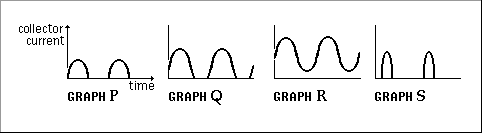
The collector current of an amplifier biased in Class A mode is illustrated in:
A. Graph P
B. Graph Q
C. Graph R
D. Graph S
And now for the answer to our June 12, 2019 TechNet Puzzle
(It is in “Invisotext” and will be visible if you highlight the area below!)
For this question you need to understand what different “class” amplifiers mean – in the case of “A”, “B”, and “C” it describes the portion of the alternating signal that is linearly amplified. The most linear, distortion-free mode, Class “A” amplifies through the entire cycle, from zero, to positive maximum, back to zero, to negative maximum and back to zero! It has the least nonlinearity BUT is the least efficient mode.
Class “B” amplifies only one half of each cycle – from zero to positive maximum and back to zero.
Class “AB” is somewhere between the amount of each cycle that classes “A” and “B” are amplified.
Class “C” amplifies even less of each cycle than in class “B”.
With all that under your belt, a quick look at the illustrations show that only one of them appear to have both halves of their sinusoidal curves demonstrated – Graph “R”.
So, the answer is “C” Graph R
The KCRC TechNet Puzzle for June 12, 2019
Capacitance and inductance make up a parallel resonant circuit.
If the inductance is decreased to one quarter of its original value, what will happen to the resonant frequency?
A. It will decrease to a quarter of its original value.
B. It will halve.
C. It will double.
D. It will increase by 4 times.
And now for the answer to our June 12, 2019 TechNet Puzzle
(It is in “Invisotext” and will be visible if you highlight the area below!)
I’m sorry, but sometimes you just have to understand a bit of the mathematics of electronics. The frequency of a tuned circuit is calculated by the equation:
So, L is decreased to L/4 inside the square root function of the equation, so the denominator would change by ½, doubling the previous final calculation.
Which is a long way of saying that by quartering the inductance, doubles the resonant frequency!
So, the answer is “C” Double!
.
The KCRC TechNet Puzzle for May 8, 2019
The graph below shows the voltage and current in a:
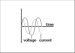
A. Capacitor
B. Resistor
C. Inductor
D. Diode
And now for the answer to our May 8, 2019 TechNet Puzzle
(It is in “Invisotext” and will be visible if you highlight the area below!)
Is it “current lags voltage” or “current leads voltage”? Just think about it a bit:
If you take a capacitor and apply a voltage potential, the capacitor starts quickly charging at its maximum rate. As the charge develops the current grows less and less and stops when the plate is fully charged – current leads voltage.
If you take a resistor and apply a voltage potential, the current produced remains the same. With an alternating current source, the current and the voltage are perfectly in phase – neither “lags” nor “leads”.
If you take an inductor and apply a voltage potential, the inductor starts building a magnetic field, limiting the current until it builds up completely and then passes current uninhibited. With an alternating current source, the current lags the voltage – the opposite of the illustration above.
A diode will conduct only during one half of the alternating cycle, and that half-wave’s current/voltage waves would be in phase.
So, the answer is “A” Capacitor!
The KCRC TechNet Puzzle for April 24, 2019
The power reflected back from an antenna can be measured with:
A. An SWR. meter.
B. A digital frequency counter
C. An oscilloscope
D. A dummy load
And now for the answer to our April 24, 2019 TechNet Puzzle
(It is in “Invisotext” and will be visible if you highlight the area below!)
“B”, a digital frequency counter shows the frequency of the signal inputted, “C”, an oscilloscope shows signal amplitude vs time, “D”, a dummy load supplies 50 ohms of pure resistance impedance to your transmitter’s output.
Which leaves us with “A”, an S.W.R. meter, which measures forward and reverse power running through the transmission line. With those values it can calculate the Voltage Standing Wave Ratio, so the answer is:
(A) An Standing Wave Ratio meter (S.W.R.)
The KCRC TechNet Puzzle for April 10, 2019
If your monitor on your computer distorts when you transmit on 80 meters, to remove this, you should:
A. Reduce the resolution of his monitor
B. Re-boot the computer
C. Change to a screened mains lead
D. Fit ferrite rings on the cable between monitor and computer
And now for the answer to our April 10, 2019 TechNet Puzzle
(It is in “Invisotext” and will be visible if you highlight the area below!)
You’re getting RF into your monitor, that it doesn’t want and can’t deal well with.
Short of locking it up in a Faraday Cage, placing ferrite RF chokes on any cable going into or out of your monitor will help diminish routes for RF to sneak into your monitor, by increasing the impedance that any common code currents will have to deal with.
The correct answer is ‘D’.
The KCRC TechNet Puzzle for March 27, 2019
A radio signal in the ionosphere ‘will have the greatest range in a single ‘bounce’ when it is returned to earth from which layer?
A. D region
B. E layer
C. F1 layer
D. F2 layer.
And now for the answer to our March 27, 2019 TechNet Puzzle
(It is in “Invisotext” and will be visible if you highlight the area below!)
The easiest way to think about this question is that the higher the ionospheric layer, the farther the RF’s ‘bounce’. There’s a good reason how ionospheric layers get named – the ‘D’ layer is closest to Earth’s surface.
Further out you will find the ‘E’ layer, then the ‘F1’ layer and finally the ‘F2’ layer being the farthest away from the surface of the Earth.
The bigger the distance from the Earth the bigger the ‘bounce’ – so answer ‘D’ “the F2 layer” is the correct answer!
The KCRC TechNet Puzzle for March 13, 2019
Why are the radial elements of a quarter wave ground plane antenna often made to droop?
A. To match 50-ohm coaxial cable.
B. To increase the angle of maximum radiation.
C. To avoid RF flowing on the outer of the feeder.
D. To prevent static build up on the vertical element.
And now for the answer to our March 13, 2019 TechNet Puzzle
(It is in “Invisotext” and will be visible if you highlight the area below!)
It helps to know how antennas work. A ¼ wave ground plane vertical antenna is equivalent to one half of a half wave dipole. Resonant half-wave dipoles in free space possess a nominal impedance of 73 ohms, a quarter-wave ground plane vertical is half of that, 36 ohms in free space, BUT if you droop those radials downward you can increase its impedance at resonance all the way to 50 ohms! You can also position the ground planes to a specific height with regard to Earth ground, to obtain a 50-ohm impedance, but ‘A’ is the best answer for this question.
.
The KCRC TechNet Puzzle for February 27, 2019
What frequency would you tune your radio to check that you were not radiating any spurious harmonics from your transmissions on 29.0 MHz?
A. 29.0 MHz
B. 43.5 MHz
C. 52,5 MHz
D. 58.0 MHz
And now for the answer to our February 27, 2019 TechNet Puzzle
(It is in “Invisotext” and will be visible if you highlight the area below!)
You just have to know how ‘harmonics’ works. The ‘first harmonic’ of 29.0 MHz is 29.0 MHz, where your signal belongs. Its ‘second harmonic’ is twice its primary frequency, or 58.0 MHz in this case.
So, the correct answer is ‘D’, 58.0 MHz.
The KCRC TechNet Puzzle for February 13, 2019
“ALC” stands for:
A. Automatic Level Control
B. Audio Low-pass Coil
C. Alternating Local Current
D. Antenna Loading Choke
And now for the answer to our February 13, 2019 TechNet Puzzle
(It is in “Invisotext” and will be visible if you highlight the area below!)
Sometimes ya just gotta know what an abbreviation stands for. In this case it’s just an abbreviation for Automatic Level Control, choice ‘A’.
ALC is a safety feature used with linear amplifiers, so that they are not overdriven beyond their linear range of amplification. Originally, they were designed to feed an increasing negative grid current into the final amplifier tube of a tube-based transmitter, when the linear amplifier detected that the driver power was too high. Although most transmitters are solid state, the ALC remains a negative voltage potential increasing in voltage as the transmitter’s driving power goes higher and higher beyond the linear amplifier’s design specification for an input drive for linear operation.
Technically, it operates much like a receiver’s Automatic Gain Control, except for transmitter power, instead of receiver gain, and is more of a safety feature, than a way to limit your hearing loss from too much receiver gain blowing out your eardrums. Often the ALC uses the same drive limiting circuitry that allows your transmitter to “fold back” transmitter power if your SWR is detected to be too high.
The KCRC TechNet Puzzle for January 23, 2019
To receive CW, a suitable bandwidth for the IF filter is:
A. 25 Hz
B. 250 Hz
C. 2.5 kHz
D. 25 kHz
And now for the answer to our January 23, 2019 TechNet Puzzle
(It is in “Invisotext” and will be visible if you highlight the area below!)
The simplest way of thinking about this question, is to ask what bandwidth would be required to receive Morse code. I don’t know about you, but 25 Hz is subsonic and inaudible to me, so ‘A’ isn’t the correct answer. A bandwidth of 2.5 kHz would be fine for SSB phone transmissions, but it’s wasteful for CW, and 25 kHz would be closer to the bandwidth of an FM signal, but even more wasteful for CW.
So, the best answer in this case would be 250 Hz, answer ‘B’.
.
The KCRC TechNet Puzzle for January 9, 2019
The block diagram of the sideband generator of an SSB transmitter is drawn below.
What will a probe at point ‘S’ reveal?

A. Carrier plus one sideband
B. Carrier only.
C. Carrier plus two sidebands
D. Two sidebands
.And now for the answer to our January 9, 2019 TechNet Puzzle
(It is in “Invisotext” and will be visible if you highlight the area below!)
Well, if you just look at the labels on the illustration, it seems self-evident that a probe at point ‘S’ would contain only a carrier, but let’s discuss how an SSB transmitter works.
We start with an audio frequency microphone signal – your voice (seen by a probe at point ‘P’). Then we need to generate the RF signal that will propagate through the ionosphere to that distant receiver. That is what the carrier oscillator is designed to do. If we only used a carrier oscillator, all we would have is a CW transmitter, but we are building an SSB transmitter. When alternating currents with different frequencies are ‘mixed’ together in a nonlinear device, this interaction produces additional signals that are the sum and the difference of the two original frequency signals. A ’Balanced Modulator’ is a special kind of mixer – it mixes the carrier frequency with the audio frequency, generating ‘sideband’ frequencies: the sum of the carrier wave frequency and the audio frequency for the upper sideband and the difference between the carrier wave frequency and the audio frequency for the lower sideband. The Balanced modulator also filters out the original carrier wave frequency from the newly created two sidebands (seen by a probe at point ‘Q’).
At this point, you have a double sideband transmission – but all you need is the upper or the lower sideband to get your transmission to be readable.
That is what the filter is for – to remove one of the sidebands, giving you a single sideband signal at probe point ‘R’ – ready for further linear amplification before it goes to the antenna to be radiated to the person that you are communicating with!
So, the correct answer is that a probe at point ‘S’ will show only the carrier signal, choice ‘B’!